These modules were originally going to be a large yard representing the ex-L&N Goulding Yard in Pensacola but I'm leaning toward making them a generic staging yard that can be used at the end of a module set or possibly split to use as stub staging at the ends of a point-to-point modular setup.

Each module is 1'x6' and utilizes a 6" deep birch ply end plate. The legs are 1x2 ripped from wider stock and are hinged. A folding brass plated brace is used on each leg set on opposite sides. The frames and leg sets are painted with satin black to provide a finished appearence as well as help with sealing the wood to avoid changes with humidity since these modules may well travel to shows and be exposed to a variety of environments. A planned rail head height of 50" and the 12" module width does not provide the utmost stability on idividual modules. However, my past experience with modular setups shows stabilty increases as modules are added ...especially once curves or corner modules are employed. So when setup for operation the stability should be more than adequate.
.JPG)
Eye bolts and t-nuts were used to provide leveling and height adjustment capability for each module. Eye bolts were chosen since they allow easy adjustment by hand. First, a hole was drilled to accept the t-nut and allow depth for the length of the eye bolt.
.JPG)
Next the t-nut was tapped into place with a hammer.
.JPG)
Then an eye bolt with its stop nut was inserted.
.JPG)
Finally, the eye bolts were adjusted as needed to provide level stance for the modules and the stop nut was snugged against the t-nut. This adjustment can be easily changed when the modules are moved.
.JPG)
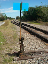
Finally, a parting shot showing a few pieces of rolling stack and a couple of Atlas code 55 #7 turnouts to give an idea of the real estate available for development!
+(Medium).JPG)
No comments:
Post a Comment